eFatigue gives you everything you need to perform state-of-the-art fatigue analysis over the web. Click here to learn more about eFatigue.
Constant Amplitude Crack Growth Technical Background
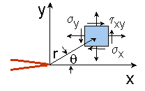
All fatigue cracks have very large stress concentrations associated with them. Traditional methods and material properties are not able to describe the behavior of a cracked structure. Instead fracture mechanics is used. Fracture mechanics is a way of computing the stress and strain fields around a crack. For an isotropic elastic material, the stress in the neighborhood of a crack can be easily computed.

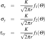
The stresses at any location r and θ from the crack tip are given by

The parameter K is a measure of the magnitude of the stress field in the region of the crack tip and is called the stress intensity factor. Two cracks with the same stress intensity will have the same behavior.
The general form of the stress intensity solution for any crack can be described as:

Each of the terms accounts for a specific aspect of the crack geometry or loading.

Ms is a correction for a crack at a free surface. For a through edge crack in a uniform stress field Ms = 1.12. For the same crack emanating from a notch Ms can be approximated as Ms = 1.12 Kt where Kt is the stress concentration factor of the notch. Surface cracks will also depend on the crack aspect ratio a/2c. Complicated stress distributions and crack shapes will have complicated Ms factors.
Mt is a correction factor for the free surface ahead of the crack. A simple correction for a through crack is

This accounts for the changing net section area as the crack grows. For a surface crack, when a → b the crack will have grown through the thickness and become a through crack. During this process the aspect ratio will continue to change.
Φ accounts for the aspect ratio of the crack. A semicircular crack will have Φ = π/2 while a through thickness crack has Φ = 1.
The stress intensity factor for a particular geometry and loading is determined from the combined effects of all of these effects and usually written as

Material Properties
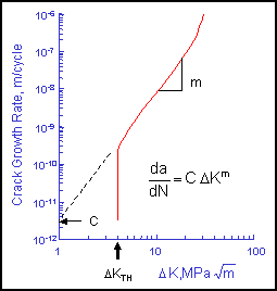
Crack growth analysis requires a crack growth curve for the material. The linear portion of the curve represents stable crack growth and is characterized by an intercept, C, and slope, m. The cyclic stress intensity ΔK is computed from the applied stresses and crack length.

The rate at which a crack grows depends on both stress range and crack size. Cracks are assumed not to grow under compression loading.

The threshold stress intensity, ΔKTH, represents a stress intensity below which cracks will not grow. This is analogous to the fatigue limit in traditional fatigue analysis. Cracks will not grow unless the initial size, ai, and stress range Δs, are large enough to be above the threshold stress intensity.

Stress Intensity Factor
The general form of the stress intensity solution for any crack can be described as:

Each of the terms accounts for a specific aspect of the crack geometry or loading. The stress intensity finder combines all of the loading and geometric variables into a single function F(a) to compute the stress intensity.

Unlike traditional stress concentration factors, Kt, stress intensity factors are usually a function of the crack size. They tend to increase as the crack becomes larger. Under a constant stress level, a crack grows faster as it gets longer. In fracture mechanics, the stress is always taken as the gross section stress in the absence of a crack. The effect of the decreasing cross section area is accounted for in the F(a) term.
Care must be used in determining the correct crack size. For a surface crack, the most important dimension is the crack depth, a, rather than the length along the surface, 2c. The most damaging part of a surface crack is the dimension that you do not see on the surface. Most surface cracks have a semi-elliptical shape.

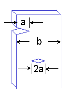
Some cracks are described with a length of 2a rather than a.

The edge crack has only one crack tip and one free surface so that it can only grow in one direction. The center crack has two crack tips and no free surfaces. Each side of the crack grows as if it had a length of a in a plate of width b/2.
Integration
The cycles required to grow a crack from its initial size, ai, to any other size, af, is computed by integrating the materials crack growth rate with the appropriate stress intensity factor.

Numerical integration is used to solve this integral. Selection of an appropriate initial crack size requires some knowledge of the structure. Structures often contain cracks on the order of a millimeter and this would be a good estimate in the absence of any other information. The analysis is not very sensitive to the choice of final crack size and any reasonable estimate may be used.