- Fatigue Technologies
- Constant Amplitude
- Variable Amplitude
- Finite Element Model
- Fatigue Analyzers
- Finders
- Technical Background
- Multiaxial
- Probabilistic
- High Temperature
- Welded Structures
- Cast Iron
- Small Defect √ Area
- Utilities
- Languages
 日本語
日本語eFatigue gives you everything you need to perform state-of-the-art fatigue analysis over the web. Click here to learn more about eFatigue.
Finite Element Model Supported File Types
Three formats are currently supported:
ABAQUS .fil FEA File Format
ABAQUS FEA models are supported through the stress results in the .fil file. Both ASCII and binary formats are supported.
In addition to the plotting provided by eFatigue web site you can download the fatigue results and use your standard viewer.
The fatigue contours are exported to a newly created .fil file. The fatigue results .fil file contains one stress increment. Each tensor item contains a separate life plot. The title for the increment indicates what each tensor represents.
A sample title would be:
-1*LOG10(LIFE) SX-Worst; SY-Goodman; SXY-Findley; |
This indicates that there are 3 life contours. All are �1*LOG10(Life). The three lives are stored in the SX, SY and SXY stress tensors.
The title of the exported results is shown in the Analysis Results section of the web page after an analysis is completed.
Supported Elements
All elements with Cartesian stress tensors are supported. This includes solids, membranes, 2-d and shell elements.
Strain Support
ABAQUS has very flexible support of strain data. The two primary strain variables are E and LE used for linear and non-linear analyses respectively. Both variables are supported.
In the case of thermal analyses strains are split into constituents caused by different phenomena. The four components are elastic strain (EE), plastic strain (PE), thermal strain (THE) and creep strain (CE). For room temperature fatigue we are only interested in the strains due to stresses, these are the elastic (EE) and plastic strains (PE).
The ABAQUS input deck controls which strain variables are written to the .fil file.
Extraction of PE and EE will take precedence over extraction of either E or LE from the .fil file.
Supported Data Locations
ABAQUS exports stress data in a number of locations. eFatigue supports the following positional data types:
- Element Nodes (Element)
- Nodal Averaged (Nodal)
- Whole Element
- Integration Points
- Element Centroidal
In reading in data the priority is as specified in the list above.
It is recommended that Element Nodes data is used as it will always include the element surface for all element types.
If a .fil file contains more than one set of positional data the list of available increments will be shown once for each set of positional data. In the example below the 4 steps are stored at 3 locations.
If you wish to analyse element nodal data define the loading as 1-4. If you wish to analyse integration point data define the loading as 9-12.
| Minimum | Maximum | ||
|---|---|---|---|
| 1) | 1.2 [Element] STEP 1.] APPLY PRESCRIBED BOLT LOADS | -231 | 585 |
| 2) | 2.1 [Element] STEP 2.] SUBSTITUTE BOLT LOAD WITH RESULTANT LENGTH CHANGE | -231 | 585 |
| 3) | 3.6 [Element] STEP 3.] APPLY PRESCRIBED THERMAL LOAD | -339 | 1030 |
| 4) | 4.4 [Element] STEP 4.] RETURN TO AMBIENT TEMPERATURES | -231 | 634 |
| 5) | 1.2 [Nodal] STEP 1.] APPLY PRESCRIBED BOLT LOADS | -231 | 585 |
| 6) | 2.1 [Nodal] STEP 2.] SUBSTITUTE BOLT LOAD WITH RESULTANT LENGTH CHANGE | -231 | 585 |
| 7) | 3.6 [Nodal] STEP 3.] APPLY PRESCRIBED THERMAL LOAD | -339 | 1030 |
| 8) | 4.4 [Nodal] STEP 4.] RETURN TO AMBIENT TEMPERATURES | -231 | 634 |
| 9) | 1.2 [Integration Point] STEP 1.] APPLY PRESCRIBED BOLT LOADS | -231 | 585 |
| 10) | 2.1 [Integration Point] STEP 2.] SUBSTITUTE BOLT LOAD WITH RESULTANT LENGTH CHANGE | -231 | 585 |
| 11) | 3.6 [Integration Point] STEP 3.] APPLY PRESCRIBED THERMAL LOAD | -339 | 1030 |
| 12) | 4.4 [Integration Point] STEP 4.] RETURN TO AMBIENT TEMPERATURES | -231 | 634 |
Plotting Results
The ABAQUS viewer does not support contouring of .fil files. So you should load your .fil fatigue results into your standard .fil viewer in a similar manner to any structural results.
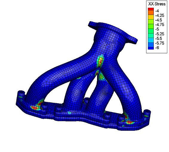
A sample Worst life plot (Sx) is shown below, The contour shows -1*LOG10(Life) - i.e. -6 is a life of 106 repeats and -4 is a life of 104 repeats.
ANSYS FEA File Format
ANSYS FEA data is supported via the structural results file, extension .rst. Versions 9 and above of ANSYS .rst files are supported. The .rst file must contain geometry.
In addition to the plotting provided by eFatigue web site you can download the fatigue results and use your standard viewer.
The fatigue contours are exported to a newly created .rst file. The fatigue results .rst file contains one stress increment. Each tensor item contains a separate life plot. The title for the increment indicates what each tensor represents.
A sample title would be:
| -1*LOG10(LIFE) SX-Worst; SY-Goodman; SXY-Findley; |
This indicates that there are 3 life contours. All are �1*LOG10(Life). The three lives are stored in the SX, SY and SXY stress tensors.
The title of the exported results is shown in the Analysis Results section of the web page after an analysis is completed.
Supported Elements
All SOLID, PLANE, SHELL and SOLIDSHELL elements are supported. These relate to the following ANSYS routine numbers:
| - | PLANE2 | - | - | SOLID5 | - | - | - | - | - |
| - | - | PLANE13 | - | - | - | - | - | - | - |
| - | - | - | - | PLANE25 | - | - | SHELL28 | - | - |
| - | - | - | - | PLANE35 | - | - | - | - | - |
| SHELL41 | PLANE42 | SHELL43 | - | SOLID45 | SOLID46 | - | - | - | - |
| SHELL51 | - | PLANE53 | - | PLANE55 | - | SHELL57 | - | - | - |
| SHELL61 | SOLID62 | SHELL63 | SOLID64 | SOLID65 | - | PLANE67 | - | SOLID69 | SOLID70 |
| - | SOLID72 | SOLID73 | - | PLANE75 | - | PLANE77 | PLANE78 | - | - |
| - | PLANE82 | PLANE83 | - | - | - | SOLID87 | - | - | SOLID90 |
| - | - | - | - | SOLID95 | SOLID96 | SOLID97 | SOLID98 | SHELL99 | - |
| - | - | - | - | - | - | - | - | - | - |
| - | - | - | - | - | - | SOLID117 | - | - | - |
| PLANE121 | SOLID122 | SOLID123 | - | - | - | SOLID127 | SOLID128 | - | - |
| SHELL131 | SHELL132 | - | - | - | - | - | - | - | - |
| - | - | SHELL143 | - | PLANE145 | PLANE146 | SOLID147 | SOLID148 | - | SHELL150 |
| - | - | - | - | - | - | SHELL157 | - | - | - |
| - | PLANE162 | SHELL163 | SOLID164 | - | - | - | SOLID168 | - | - |
| - | - | - | - | - | - | - | - | - | - |
| SHELL181 | PLANE182 | PLANE183 | - | SOLID185 | SOLID186 | SOLID187 | - | - | SOLSH190 |
| SOLID191 | - | - | - | - | - | - | - | - | - |
| - | - | - | - | - | - | - | SHELL208 | SHELL209 | - |
| - | - | - | - | - | - | - | - | - | - |
| - | - | PLANE223 | - | - | SOLID226 | SOLID227 | - | - | PLANE230 |
| SOLID231 | SOLID232 | PLANE233 | - | - | SOLID236 | SOLID237 | - | - | - |
| - | - | - | - | - | - | - | - | - | - |
| - | - | - | - | - | - | - | - | - | - |
| - | - | - | - | - | - | - | - | - | - |
| - | SOLID272 | SOLID273 | - | - | - | - | SOLID278 | SOLID279 | - |
| SHELL281 | - | - | - | SOLID285 | - | - | - | - | - |
| - | - | - | - | - | - | - | - | - | - |
Strain Support
ANSYS .rst files automatically contain the strain tensors split into elastic and plastic components. Where appropriate to the analysis the strains will be extracted and stored in the two components EE and PE.
Plotting Results
To plot the fatigue results in ANSYS perform the following steps.
- Run ANSYS
- From ANSYS Main menu pick the General Postproc menu item Results Viewer.
- This will request the .rst filename, pick the file of interest.
- On toolbar there will be a series of combo/drop-down boxes. On the left hand one select Element Solution - Stress - X Component of Stress. The component will depend upon which life contour you require.
- Press Plot Results tool. This is first tool on toolbar after drop-down boxes.
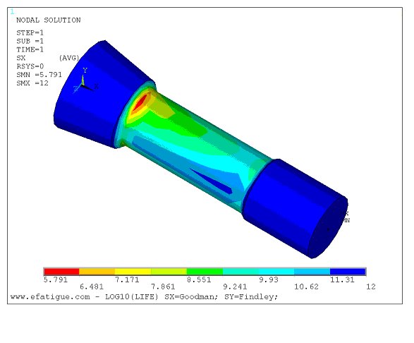
A sample Worst life (Sx) plot is shown below:
Pro Mechanica ASCII FEA File Format
Pro Mechanica FEA models are supported through the ASCII version of the .neu file and .s01,.s02 etc stress results files.
The .neu file is used for the h-element/h-node version of the model geometry and connectivity. The .s01, .s02 etc files are used for the stress and strain data
So unlike most of the other FEA formats multiple files need to be uploaded for a Pro-Mechanica model.
When validating an FEA model the .neu file should be used.
The fatigue contours can be exported to an ASCII results file. They are also automatically exported to a eFatigue 3d plot contour that can be plotted using the eFatigue 3d viewer.
Supported Elements
All elements with Cartesian stress tensors are supported. This includes solids, membranes, 2-d and shell elements.
By default Pro-M uses tetrahedrons and octahedrons for h-element meshing. Currently octahedrons are not one of the directly supported eFatigue elements so they are stored as 2 back-to-back pyramids.
Strain Support
Pro-Mechanica strain data is supported.
Supported Data Locations
Pro-Mechanica exports all stress and strain data as Nodal Averaged (Nodal) data at h-nodes. eFatigue imports this nodal data.
Plotting Results
In addition to the plotting provided by eFatigue web site you can download the fatigue results and use the eFatigue 3d viewer.
Solidworks and COSMOS/M ASCII FEA File Format
All files associated with a Solidworks FEA analysis must be stored in a single folder/directory on the eFatigue server.
Only the files for the analysis should be stored in the folder.
It is important that you do not store more than one set of analysis results in a folder as this will cause the model validation to fail.
The files required to define an analysis are:
- the geometry file
- one component stress file for each step containing the stress tensors
- one component strain file for each step if the analysis is elastic-plastic
After uploading the FEA analysis files the Geometry file should be used to validate the Finite Element Model.
The remainder of the files in the folder will be checked to see if they contain stress or strain tensors.
Ideally you should name your stress and strain files starting with the step number so that the stress steps will appear in the correct order.
|
i.e. 1_stresses.txt 1_strains.txt 2_stresses.txt 2_strains.txt |
So unlike most of the other FEA formats multiple files need to be uploaded for a Solidworks model.
The description information in the header of the tensor stress and strain files is used to match the stresses and strains for a particular step.
The results contours from the fatigue analysis can be exported to an ASCII results file. They are also automatically exported to a eFatigue 3d plot contour that can be plotted using the eFatigue 3d viewer.
Geometry File
The geometry file is in the COSMOS/M Input format as defined in Appendix F of the COSMOS/M User's Guide.The first few lines will be similar to:
C* Units = 0 |
ND, 1, -0.0057249996 -0.006325 0 |
Stress Tensor Files
There should be a separate stress tensor file for each step/increment. The file format is the print from Solidworks.See the section How to Export ASCII data from Solidworks below for how to do create this file in Solidworks.
You can name the file containing each step's stresses in any way but it is recommended that the file name begins with the step number.
An example of the first few lines of a stress file is shown below:
15:09, Friday, December 09, 2011 |
Strain Tensor Files
These files are only required if the analysis was elastic-plastic.There should be a separate strain file for each step/increment. The file format is the print from Solidworks.
See the section How to Export ASCII data from Solidworks below for how to do create this file in Solidworks.
You can name the file containing each step's strains in any way but it is recommended that the file name begins with the step number.
An example of the first few lines of a strain file is shown below:
15:09, Friday, December 09, 2011 |
How to Export ASCII data from Solidworks
To export the geometry:- In the simulation tree, right mouse click on the study name of interest.
- This will display a menu. Select the item 'Export...'.
- The 'Save As' dialogue box opens.
- Define a suitable filename.
- From the 'Save as type' drop down select 'Simulation Files (*.geo)'. (Note that the .geo file is an ASCII file and can be renamed to .txt after exporting).
- Click the 'Options' button, this will display the 'Export Options - COSMOSM' dialogue.
- Select the 'FEM only' radio button to export the model.
- Press 'OK' to close the 'Export Options COSMOSM' dialogue.
- Press 'Save' on the 'Save As' dialogue.
After exporting the model, To export the stresses:
- In the simulation tree right click on the 'Results' item associated with the study name of interest. On the resulting menu select the item 'List Stress, Displacement, Strain'.
- This will display the 'List Results' dialogue.
- In the 'Advanced Options' section, select the 'Nodes' radio button. Then click on 'Range'. This allows the export of the stress results for all nodes in the model.
- In the 'Quantity' section select the 'Stress' radio button.
- In the 'List Set' select 'List normal and shear stresses'.
- In the resulatnt 'List Results' window press the 'Save' button to save to a text file.
If your analysis was elastic-plastic then repeat the results export for the strain tensors. The process is identical to that defined for the stresses, excpet in the 'Quantity' section select the 'Strain' radio button rather than the 'Stress' one.
The resultant file should look similar to the strain tensor example file shown above.
Supported Elements
All elements with Cartesian stress tensors are supported. This includes solids, membranes, 2-d and shell elements.
Strain Support
Strain data is supported.
Supported Data Locations
Only Nodal Averaged (Nodal) data is supported for Solidworks.
Plotting Results
In addition to the plotting provided by eFatigue web site you can download the fatigue results and use the eFatigue 3d viewer.
eFatigue ASCII FEA file format
Format
The eFatigue ASCII FEA file format is a multi line ASCII file. Each line can define:
- A Nodal Location
- Element type and a list of nodes on the element
- List of Shell Layers
- An Increment - used as a wrapper for analysis data such as stresses
- Stress data for an individual node
The ASCII FEA file is structured as shown below:
|
NODAL POSITIONS (list of nodal position data) ELEMENTS (list of elements data) SHELL (parameters) INCREMENT (parameters) DATA TYPE (parameters) ELEMENT TYPE (parameters) (list of increment data) |
Items in Italics are not required in all models.
If your data is from a multi-part model then PART statements can be inserted within the NODAL POSITIONS, ELEMENTS and INCREMENT list data to define which part the statement applies to.
Nodal Positions
Nodal positions are defined using the token NODAL POSITIONS. All lines that follow this line are assumed to be nodal position related until an increment or element node list definition is encountered.
Each line has 4 required items, the node and the co-ordinates of the node in XYZ order. An optional 5th parameter can be added if this node belongs to a shell, in this case the fifth value is the shell thickness at the node.
Part definitions within the positions list indicate that all the following positions apply to that part.
An example definition is:
NODAL POSITIONS |
Element Definition and Node Lists
Element definitions and node lists are defined using the token ELEMENTS. All lines that follow this line are assumed to be element definitions until an increment or position definition.
Each line has an element number, an element type and a list of nodes.
The order of the nodes is important as they are used to derive the faces on the element, a full definition of the expected element order is outlined in the Discussion of Elements section.
The valid element type descriptors are:
| Token | Description |
|---|---|
| Blank | Same as the last element |
| NOT3D | Neither a 3-d solid nor a shell element - Usually 2-d. |
| SHELL | A shell element. |
| ANSYS_TET4 | 4 Node 4 Face (Tet), with ANSYS node ordering |
| ANSYS_BRICK8 | 8 Node 6 Face (Brick), with ANSYS node ordering |
| ANSYS_TET10 | 10 Node 4 Face (Tet with mid side nodes), with ANSYS node ordering. Mid side nodes do NOT have stresses. |
| ANSYS_BRICK20 | 20 Node 6 Face (Brick with mid side nodes), with ANSYS node ordering. Mid side nodes do NOT have stresses. |
| ABAQUS_TET4 | 4 Node 4 Face (Tet), with ABAQUS node ordering |
| ABAQUS_BRICK8 | 8 Node 6 Face (Brick), with ABAQUS node ordering |
| ABAQUS_TET10 | 10 Node 4 Face (Tet with mid side nodes), with ABAQUS node ordering |
| ABAQUS_BRICK20 | 20 Node 6 Face (Brick with mid side nodes), with ABAQUS node ordering |
| ABAQUS_WEDGE6 | 6 Node 5 Face (wedge) |
| ABAQUS_WEDGE15 | 15 Node 5 Face (wedge with mid side nodes) |
| ABAQUS_WEDGE16_TO_18 | 16 to 18 Node 5 Face (wedge with mid side nodes, and between 1 and 3 mid surface nodes) |
| ABAQUS_BRICK21_TO_27 | 21 to 27 Node 6 Face (Brick with mid side nodes and centrodal node, and up to 6 mid surface nodes) |
Pyramids are supported as collapsed ANSYS bricks, this is outlined in the Discussion of Elements section. To import models from other formats you should match the element order and faces to one of the supported element types. You can also split unsupported elements into a number of supported elements, an example would be:Octohedrons can be split into 2 pyramids or 4 tetrahedrons.
Part definitions within the element list indicate that all the following elements apply to that part.
An example definition is:
ELEMENTS |
||
4799 ABAQUS_WEDGE6 |
2169 2172 2170 3267 3269 3268 |
|
4800 |
2181 2186 2182 3270 3272 3271 |
|
4801 ABAQUS_BRICK8 |
2107 2174 2128 2108 3273 3276 3275 3274 |
|
4802 |
2128 2129 2109 2108 3275 3278 3277 3274 |
|
4803 |
2129 2130 2110 2109 3278 3280 3279 3277 |
|
Defining Shell Layers
All of the shell layers requiring increment data should be defined in the shells list.
Shell layers are defined using the token SHELL. An example definition is:
SHELL layer=1, name=Top |
The case sensitive keywords and tokens that are associated with a shell definition are:
| Token | Description |
|---|---|
| name | Name of layer |
| layer | Layer number - this is used when defining increment data |
This statement would occur above the increment statement in the ASCII file.
Defining Parts
Parts are defined using the token PART. An example definition is:
PART Left-Rear-Wing |
A part is used to indicate that the subsequent element, nodes or increment data applies to a specific part within the model.
Defining Increments
An increment is a snapshot of data for the model, usually stresses and strains. FEA codes have different names for this snapshot, the use of the term increment is not intended to only apply to multi-increment analyses. An ASCII FEA model should have at least one snapshot of data.
Increments are defined using the token INCREMENT. An example definition is (this should all be on one line):
INCREMENT step=1, increment=7, position=Element, time=6.7, description=step 1 inc 7 time 6.7 |
The case sensitive keywords and tokens that are associated with an increment are:
| Token | Description |
|---|---|
| position | Position of data, either Nodal or Element |
| step | The step from the FEA model |
| increment | The increment from the FEA model |
| time | The time of the increment from FEA model |
| description | The description of increment |
| file | The source FEA model file |
Any data lines that follow an increment are assumed to belong to that increment.
Defining Element Types
Element types are used within an increment data list to indicate that the following data applies to 2-d elements, shells or 3-d (solid) elements.
If all elements are 3-d this statement is not required.
Element Types are defined using the token ELEMENT TYPE. An example definition is:
ELEMENT TYPE SHELL |
3 element types are supported:
- SHELL
- 2D
- 3D
All data lines after an ELEMENT TYPE statement contain data for elements of that type. The default type is 3D.
If the data type is a shell then all subsequent data lines must contain a shell number too.
Defining Data Types
Data types are defined using the token DATA TYPE. An example definition is:
DATA TYPE name=S, items=6, subnames=Sx Sy Sz Sxy Syz Sxz |
The case sensitive keywords and tokens that are associated with a data type are:
| Token | Description |
|---|---|
| name | Data type name |
| items | How many items are stored for data type. If > 1 then this is probably a tensor (6) |
| subnames | Any sub names for data, if > 1 items. |
Any data lines following this statement are assumed to be of this data type.
The following data types are used in the fatigue analysis process:
| Data Type | Description |
|---|---|
| S | Stress tensor - Sx Sy Sz Sxy Syz Sxz |
| E | Total Strain Tensor - Ex Ey Ez Exy Eyz Exz |
| EE | Elastic Strain Tensor |
| PE | Plastic Strain Tensor |
| LE | Logarithmic Strain Tensor (from ABAQUS Non-Linear Analyses). |
Data Lines
Data lines contain the data for the current increment, data type and part.
Each line contains the data for one node.
The format is (all on one line):
|
El/Node [Shell Layer] Node-Counter Data1 Data2 Data3 etc. |
The [Shell Layer] number is only required when the current element type is a shell.
NOTE: At present stresses must be stored in the order
|
Sxx Syy Szz Sxy Syz Sxz |
Example file
NODAL POSITIONS |
Downloadable examples for particular element types are provided in the next section of the help.
Discussion of Elements
The following element types are supported in the ASCII FEA format:
There may be more than one way of defining the elements, the differences allow for the differing techniques used by ANSYS and ABAQUS to define the elements. The order in which the nodes on an element are defined is used by eFatigue to derive the faces on the elements. This is used throughout the FEA fatigue software for surface detection, stress gradient effects and for plotting the results.Shells 
For 3 and 4 node shells elements ANSYS and ABAQUS have an identical node order.
ABAQUS supports 6 and 8 node shell elements, the mid-side nodes have stresses.
ANSYS also supports 6 and 8 node shell elements however only the corner nodes (3 or 4) have stresses so using this technique for importing stress data into eFatigue is of little use.
Shells have data values (stresses) at multiple layers through the thickness of the element.
The node order of the shell element is important and should be as shown in the figure, table and example below:
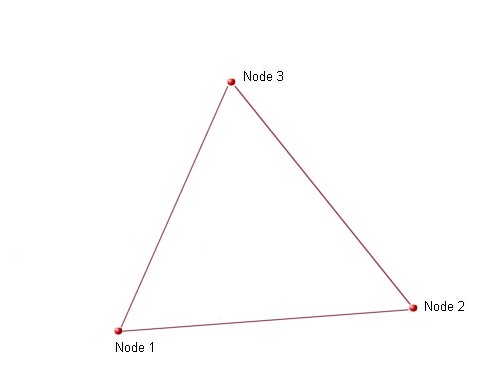
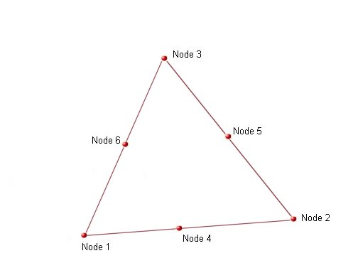
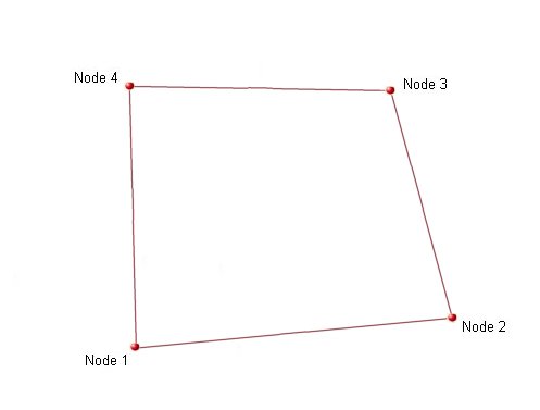
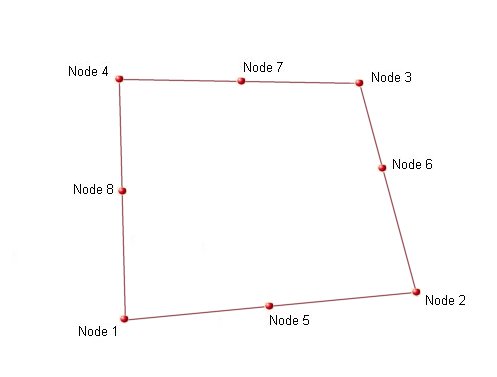
The node order in a clockwise manner is
| No. Nodes on Element | Nodes (clockwise) |
|---|---|
| 3 | 1-3-2 |
| 6 | 1-(6)-3-(5)-2-(4) |
| 4 | 1-4-3-2 |
| 8 | 1-(8)-4-(7)-3-(6)-2-(5) |
Within the ASCII FEA file the ELEMENTS section of the file should contain:
ELEMENTS |
For each shell layer there will be one set of elemental stresses for each node (3, 4, 6 or 8), and one set for each node if the stresses are nodal.
The shell layers are defined using a series of SHELL statements:
SHELL layer=1, name=Top |
And for each stress value there should be 9 values, the element or node number, the shell layer, the item counter and 6 stresses.
In the example below data is defined for layers 1 and 3 on element 17:
17 1 1 +2.368E-1 -2.626E-3 +6.248E-4 +8.046E-3 +6.625E-3 -9.807E-3 |
Example Shell Models
2-d/Plane
For 3 and 4 node 2-d elements ANSYS and ABAQUS have an identical node order. ABAQUS also has 6 and 8 node 2-d elements, they have mid-side nodes with stresses.
ANSYS also supports 6 and 8 node 2-d elements however only the corner nodes (3 or 4) have stresses so using this technique for importing stress data into eFatigue is of little use.
The node order of the 2-d element is identical to that described for SHELL elements.
Within the ASCII FEA file the ELEMENTS section of the file should contain:
ELEMENTS |
For 2-d data elemental stresses will have one value for each node (3, 4, 6 or 8), and will have one value for each node if the stresses are nodal.
Example 2-d Models
Solid Tetrahedrons
Solid tetrahedron elements are supported using both the ANSYS and ABAQUS techniques of storing these elements.
For 4 node tets ANSYS and ABAQUS have an identical node order. ABAQUS also supports 10 node tets, they have mid-side nodes with stresses.
ANSYS also supports 10 node tets however only the corner nodes (4) have stresses so using this technique for importing stress data into eFatigue is of little use.
The node order of the tetrahedron is important and should be as shown in the figure, table and example below:
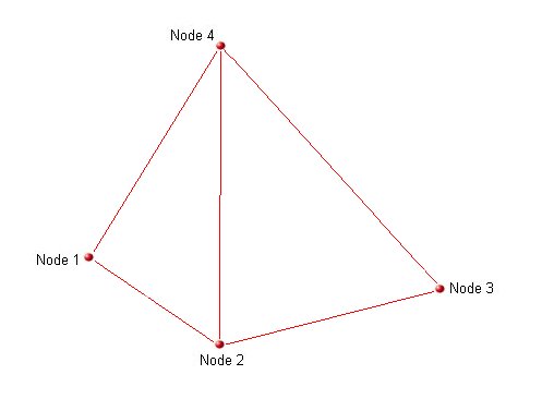
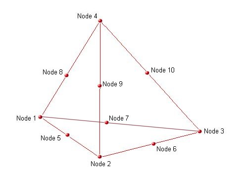
There are 4 faces. Viewing each face from the outside of the element the nodes on each face are defined as:
| Face | 4 Nodes (clockwise) | 10 Nodes inc. midsides (clockwise) |
|---|---|---|
| 1 | 1-2-3 | 1-(5)-2-(6)-3-(7) |
| 2 | 1-4-2 | 1-(8)-4-(9)-2-(5) |
| 3 | 2-4-3 | 2-(9)-4-(10)-3-(6) |
| 4 | 3-4-1 | 3-(10)-4-(8)-1-(7) |
Within the ASCII FEA file the ELEMENTS section of the file should either contain:
-
As an ANSYS 4 node tet. For the above figure and node numbers the definition for element 17 would be:
ELEMENTS
17 ANSYS_TET4 1 2 3 4
-
As an ABAQUS 4 node tet. For the above figure and node numbers the definition for element 17 would be:
ELEMENTS
17 ABAQUS_TET4 1 2 3 4
-
As an ABAQUS 10 node tet. For the above figure and node numbers the definition for element 17 would be:
ELEMENTS
17 ABAQUS_TET10 1 2 3 4 5 6 7 8 9 10
In terms of implementation the ANSYS_TET4 andf ABAQUS_TET4 tokens are interchangable. For both ANSYS and ABAQUS tet data elemental stresses will have one value for each node (4 or 10), and will have one value for each node if the stresses are nodal (4 or 10 seprate node values).
Example Single Tet Models
Solid Bricks
Solid brick elements are supported using both the ANSYS and ABAQUS techniques of storing these elements.
For 8 node bricks ANSYS and ABAQUS have an identical node order. ABAQUS also supports 20 node bricks, they have mid-side nodes with stresses.
ANSYS also supports 20 node bricks however only the corner nodes (8) have stresses so using this technique for importing stress data into eFatigue is of little use.
The node order of the brick is important and should be as shown in the figure, table and example below:
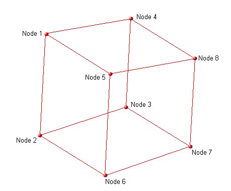
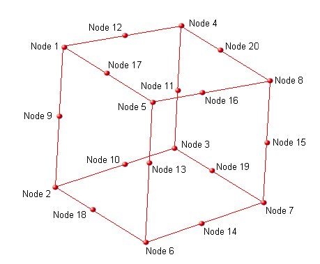
There are 6 faces. Viewing each face from the outside of the element the nodes on each face are defined as:
| Face | 8 Nodes (clockwise) | 20 Nodes inc. midsides (clockwise) |
|---|---|---|
| 1 | 1-2-3-4 | 1-(9)-2-(10)-3-(11)-4-(12) |
| 2 | 1-5-6-2 | 1-(17)-5-(13)-6-(18)-2-(9) |
| 3 | 2-6-7-3 | 2-(18)-6-(14)-7-(19)-3-(10) |
| 4 | 3-7-8-4 | 3-(19)-7-(15)-8-(20)-4-(11) |
| 5 | 4-8-5-1 | 4-(20)-8-(16)-5-(17)-1-(12) |
| 6 | 5-8-7-6 | 5-(16)-8-(15)-7-(14)-6-(13) |
Within the ASCII FEA file the ELEMENTS section of the file should either contain:
-
As an ANSYS 8 node brick. For the above figure and node numbers the definition for element 17 would be:
ELEMENTS
17 ANSYS_BRICK8 1 2 3 4 5 6 7 8
-
As an ABAQUS 8 node brick. For the above figure and node numbers the definition for element 17 would be:
ELEMENTS
17 ABAQUS_BRICK8 1 2 3 4 5 6 7 8
-
As an ABAQUS 20 node brick. For the above figure and node numbers the definition for element 17 would be:
ELEMENTS
17 ABAQUS_BRICK20 1 2 3 4 5 6 7 8 9 10 11 12 13 14 15 16 17 18 19 20
In terms of implementation the ANSYS_BRICK8 andf ABAQUS_BRICK8 tokens are interchangable. For both ANSYS and ABAQUS brick data elemental stresses will have one value for each node (8 or 20), and will have one value for each node if the stresses are nodal (8 or 20 seprate node values).
Example Single Brick Models
Solid Wedges
Solid wedge elements are supported using both the ANSYS and ABAQUS techniques of storing these elements.
The ANSYS technique is in the form of a collapsed brick, there are 6 nodes with stresses. ANSYS also supports 15 node wedges (collapsed 20 node bricks) however only the corner nodes (6) have stresses so using this technique for importing stress data into eFatigue is of little use.
ABAQUS wedges can either have 6 nodes or 15 nodes, the latter have mid-side nodes with stresses.
The node order of the wedge is important and should be as shown in the figure, table and example below:
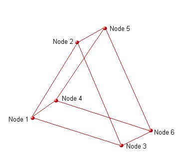
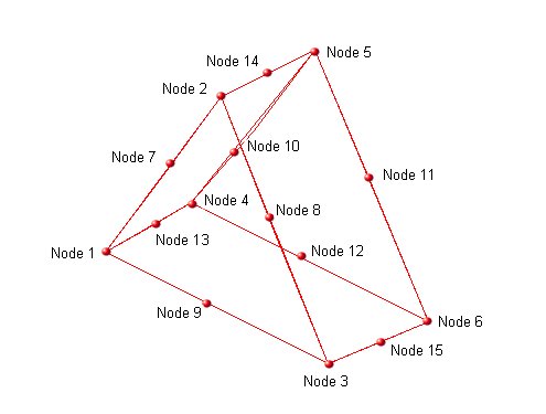
There are 5 faces. Viewing each face from the outside of the element the nodes on each face are defined as:
| Face | 6 Nodes (clockwise) | 15 Nodes inc. midsides (clockwise) |
|---|---|---|
| 1 | 1-2-3 | 1-(7)-2-(8)-3-(9) |
| 2 | 1-4-5-2 | 1-(13)-4-(10)-5-(14)-2-(7) |
| 3 | 2-5-6-3 | 2-(14)-5-(11)-6-(15)-3-(8) |
| 4 | 3-6-4-1 | 3-(15)-6-(12)-4-(13)-1-(9) |
| 5 | 4-6-5 | 4-(12)-6-(11)-5-(10) |
Within the ASCII FEA file the ELEMENTS section of the file should either contain:
-
Wedge elements defined as ANSYS BRICKS. Each element is defined with 3rd and 4th nodes identical and the 7th and 8th nodes identical. For the above figure and node numbers the definition for element 17 would be:
ELEMENTS
17 ANSYS_BRICK8 1 2 3 3 4 5 6 6
-
As an ABAQUS 8 node wedge. For the above figure and node numbers the definition for element 17 would be:
ELEMENTS
17 ABAQUS_WEDGE6 1 2 3 4 5 6
-
As an ABAQUS 15 node wedge. For the above figure and node numbers the definition for element 17 would be:
ELEMENTS
17 ABAQUS_WEDGE15 1 2 3 4 5 6 7 8 9 10 11 12 13 14 15
For ANSYS wedges the stress data can be stored either as:
-
Element stresses in which case there should be 8 sets of stress data for element 17, 3rd and 4th being identical, and the 7th and 8th being identical. For example:
17 1 +2.368E-1 -2.626E-3 +6.248E-4 +8.046E-3 +6.625E-3 -9.807E-3
17 2 +1.227E-2 +1.883E-2 -2.482E-3 -3.148E-3 -8.498E-3 +1.033E-2
17 3 -4.283E-3 +2.862E-2 +8.782E-3 -9.373E-3 -1.461E-2 +1.898E-2
17 4 -4.283E-3 +2.862E-2 +8.782E-3 -9.373E-3 -1.461E-2 +1.898E-2
17 5 +1.755E-1 +2.574E-3 -9.934E-3 +1.915E-2 +7.712E-3 -1.852E-2
17 6 +4.106E-6 +9.823E-6 +1.289E-6 +7.902E-6 -4.106E-6 -1.167E-1
17 7 +4.906E-6 +7.823E-6 +6.259E-6 +3.602E-6 -5.016E-6 -1.367E-1
17 8 +4.906E-6 +7.823E-6 +6.259E-6 +3.602E-6 -5.016E-6 -1.367E-1
-
Nodal stresses. In this case the stresses are associated with node numbers so there will only be 6 sets of stresses. For example:
1 1 +2.368E-1 -2.626E-3 +6.248E-4 +8.046E-3 +6.625E-3 -9.807E-3
2 1 +1.227E-2 +1.883E-2 -2.482E-3 -3.148E-3 -8.498E-3 +1.033E-2
3 1 -4.283E-3 +2.862E-2 +8.782E-3 -9.373E-3 -1.461E-2 +1.898E-2
4 1 +1.755E-1 +2.574E-3 -9.934E-3 +1.915E-2 +7.712E-3 -1.852E-2
5 1 +4.106E-6 +9.823E-6 +1.289E-6 +7.902E-6 -4.106E-6 -1.167E-1
6 1 +4.906E-6 +7.823E-6 +6.259E-6 +3.602E-6 -5.016E-6 -1.367E-1
Example Single Wedge Models
- ANSYS style with Elemental Stresses
- ANSYS style with Nodal Stresses
- ABAQUS style with Elemental Stresses
- ABAQUS style with Nodal Stresses
Solid Pyramids
Pyramid Elements are supported in the eFatigue ASCII FEA file in the form of collapsed bricks.
The node order of the pyramid is important and should be as shown in the figure, table and example below:
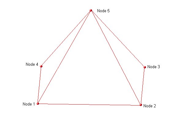
There are 5 faces. Viewing each face from the outside of the element the nodes on each face are defined as:
| Face | Nodes (clockwise) |
|---|---|
| 1 | 1-2-3-4 |
| 2 | 1-5-2 |
| 3 | 2-5-3 |
| 4 | 3-5-4 |
| 5 | 4-5-1 |
Within the ASCII FEA file the ELEMENTS section of the file should contain all pyramids elements defined as ANSYS BRICKS.
Each element is defined with the first 4 nodes being the base in a clockwise manner when viewed from beneath the element, and the last 4 nodes being the vertex node (all identical). For the above figure and node numbers the definition for element 17 would be:
ELEMENTS |
The stress data can be stored either as:
-
Element stresses in which case there should be 8 sets of stress data for element 17, the last 4 being identical. For example:
17 1 +2.368E-1 -2.626E-3 +6.248E-4 +8.046E-3 +6.625E-3 -9.807E-3
17 2 +1.227E-2 +1.883E-2 -2.482E-3 -3.148E-3 -8.498E-3 +1.033E-2
17 3 -4.283E-3 +2.862E-2 +8.782E-3 -9.373E-3 -1.461E-2 +1.898E-2
17 4 +1.755E-1 +2.574E-3 -9.934E-3 +1.915E-2 +7.712E-3 -1.852E-2
17 5 +4.106E-6 +9.823E-6 +1.289E-6 +7.902E-6 -4.106E-6 -1.167E-1
17 6 +4.106E-6 +9.823E-6 +1.289E-6 +7.902E-6 -4.106E-6 -1.167E-1
17 7 +4.106E-6 +9.823E-6 +1.289E-6 +7.902E-6 -4.106E-6 -1.167E-1
17 8 +4.106E-6 +9.823E-6 +1.289E-6 +7.902E-6 -4.106E-6 -1.167E-1
-
Nodal stresses. In this case the stresses are associated with node numbers so there will only be 5 sets of stresses. For example:
1 1 +2.368E-1 -2.626E-3 +6.248E-4 +8.046E-3 +6.625E-3 -9.807E-3
2 1 +1.227E-2 +1.883E-2 -2.482E-3 -3.148E-3 -8.498E-3 +1.033E-2
3 1 -4.283E-3 +2.862E-2 +8.782E-3 -9.373E-3 -1.461E-2 +1.898E-2
4 1 +1.755E-1 +2.574E-3 -9.934E-3 +1.915E-2 +7.712E-3 -1.852E-2
5 1 +4.106E-6 +9.823E-6 +1.289E-6 +7.902E-6 -4.106E-6 -1.167E-1